Materials
- 1 x Raspberry Pi with Scratch GPIO 5
- 1 x GPIO Breakout Board
- 1 x Breadboard (Maplin AD-01 Solderless Breadboard)
- 3 x LEDs (Green, Amber, Red)
- 3 x Resistors
- 7 x Jumper Leads
Introduction
GPIO
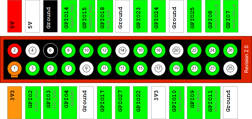
GPIO stands for General Purpose Input Output. Here is a diagram of the layout, some pins have a specific function such as pin 6 which is Ground the equivalent to a negative terminal of a battery.
We can control all of the Green labelled pins from Scratch, either setting output pins to on or off, or monitoring the state of input pins. We will use LEDs for output and a micro switch for input.
Pins 3, 5, 7, 8 & 10 are set to be input by default and the rest as output.
Breadboard
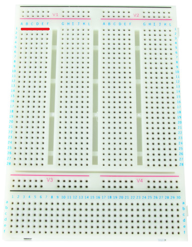
The Breadboard is like a circuit board, but it allows us to easily connect the components (LEDs, Resistors and Switches) to the GPIO Header using Jumper Leads.
The rows on the Breadboard are connected. So if you connect a Jumper Lead to pin V1-A1 then V1-B1, V1-C1, V1-D1, V1-E1 and V1- F1 will have a connection to that lead too.
LEDs & Resistors
LED stands for Light Emitting Diode. A Diode is like a one way street, it’s important to connect the positive and negative the right way around or it won’t work.
If you look closely at an LED you will notice that it has one leg longer than the other. The long leg is the positive terminal or connection.
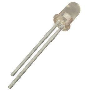
LEDs are designed to work with difference voltages, this will be lower to the output voltage from the GPIO pin. If we connected the LED directly to the GPIO pin and set the output to on it would blow the LED. So, we need to use a resistor to adjust the voltage for the LED. The Resistor needs to be connected between the GPIO pin and the positive or long leg of the LED.
Jumper Wires
Jumper wires are used to connect the components on the breadboard.

They are only needed to connect components across different rows on the breadboard, remember that the columns on a row are already connected on the board. For example, the long leg of the LED is on the same row as one end of the resistor. The short leg of the LED needs to be connected to the Ground/Negative pin of the GPIO, so we would use a jumper wire on the same row as the LED’s short leg and connect it to the same row as pin 3 on the GPIO.
Green Light
Take a Jumper Lead and plug it into V1-A6, this is connected to pin 11 on the GPIO. Connect the other end to V2-A20.
Take a Resistor and plug it into V2-B20 and V2-B19. Remember V2-A20 and V2-B20 are on the same row and therefore are connected.
Take an LED and plug the long leg into V2-C19 and the short leg into V2-C18.
Take a Jumper Lead and plug it into V2-D18 and V1-L3. V1-L3 is Ground or Negative on the GPIO.
Now when we switch the output pin 11 to on, it will send 3.3V to the Resistor which will lower the voltage sent to the LED that is connected to Ground/Negative to complete the circuit.
Code
Once you have assembled your components on the breadboard, ask a Teacher to check that everything is in the right place. The GPIO pins are connected directly to the CPU of the Raspberry Pi and a short circuit could permanently damage it.
Double click the Scratch GPIO 5 icon on the desktop. This will load Scratch with the plugins necessary to control the GPIO pins.
Select the Events group and drag and drop a When Clicked function onto the surface.
Select the Control group and Drag and drop a Broadcast function under the When Clicked function. Set the Broadcast text to “pin11on”.
Click the Green Flag to run the project and see if your green LED lights up.
What happens when you stop your project and run it again? The LED light will stay on until you set the output pin to off using a Broadcast function with the text “pin11off”.
Challenge 1
See if you can make the Green LED flash. Hint: Try adding Repeat and Wait functions to your code.
Challenge 2
Ask a Teacher to disconnect the breakout cable from the Raspberry Pi. Then, see if you can add an amber LED using GPIO pin 12. Hint: Repeat the instructions from the Green Light, using the same pattern of connections.


0 comments:
Post a Comment